Electrical Design | Circuit Schematics
IR RECEIVER | Power Supply Beacon Detector
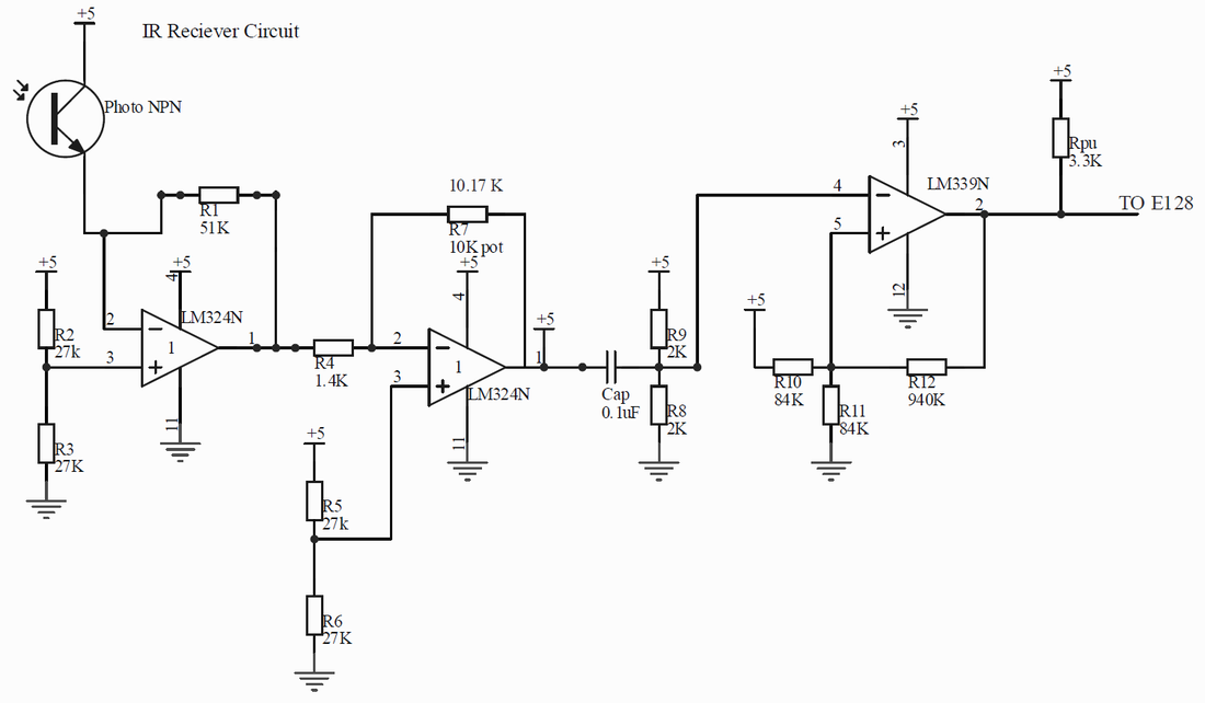
To receive IR signals from the power supply beacons. The first stage of this circuit is a trans-resistive op-amp circuit with an inverting op-amp for signal amplification (reference voltage generated from voltage divider). The signal from the second stage of amplification is passed through a high pass filter to minimize the effects of background noise. The final stage is a comparator set with hysteresis.
To receive IR signals from the power supply beacons. The first stage of this circuit is a trans-resistive op-amp circuit with an inverting op-amp for signal amplification (reference voltage generated from voltage divider). The signal from the second stage of amplification is passed through a high pass filter to minimize the effects of background noise. The final stage is a comparator set with hysteresis.
TAPE SENSOR | Sense Black Tape on Field
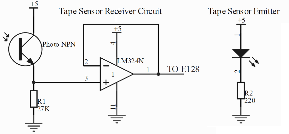
To guide the bot’s movement along the tape guides on the field. The tape sensor receiver circuit is a unity gain circuit and the emitter is a simple circuit connected to power and a grounded resistor.
To guide the bot’s movement along the tape guides on the field. The tape sensor receiver circuit is a unity gain circuit and the emitter is a simple circuit connected to power and a grounded resistor.
DC MOTOR | Wheels (2) and Launcher (1)
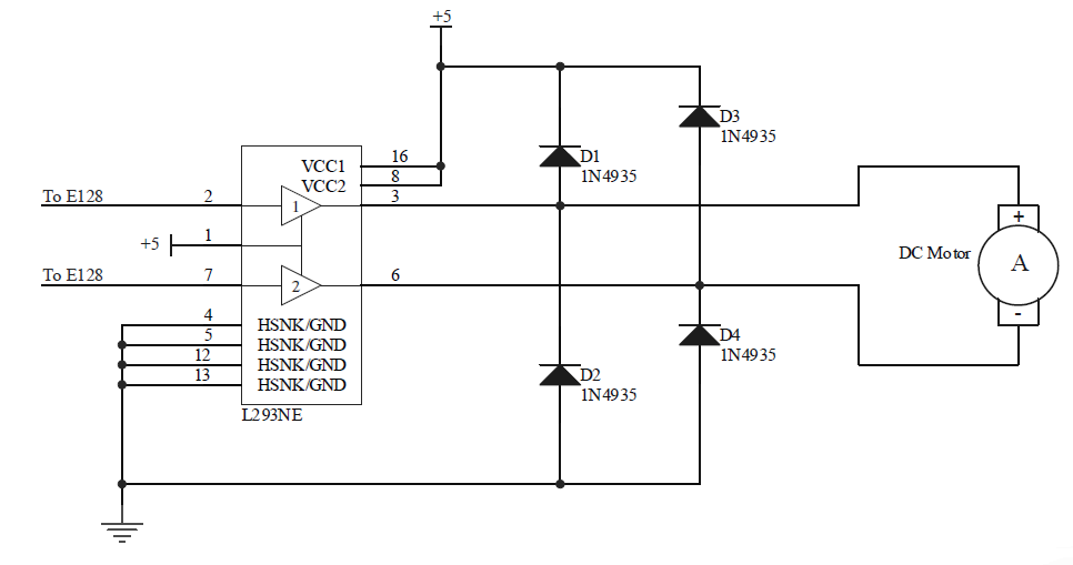
To drive motors that drive movement of the bot and launch the ball from the turret. The circuit utilizes an H-bridge (L293NE) to drive the DC motors and 4 diodes (N4935) for snubbing. The enable line (pin 1) is set high to enable control from the H-bridge while pin 2 is set to high (turn forward) or low (turn reverse) and a PWM signal is applied to pin 7.
To drive motors that drive movement of the bot and launch the ball from the turret. The circuit utilizes an H-bridge (L293NE) to drive the DC motors and 4 diodes (N4935) for snubbing. The enable line (pin 1) is set high to enable control from the H-bridge while pin 2 is set to high (turn forward) or low (turn reverse) and a PWM signal is applied to pin 7.
|
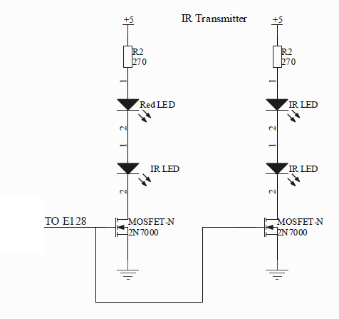
IR TRANSMITTER | Signal for Resupply Depot (1 w/ Red LED and 12 with 2 IR emitters in series)
To emit signal to the re-supply depot and request for a ball. This is a typical IR emitter circuit using an N-channel MOSFET (2n7000) with a 270 ohm resistor, a Red LED (to detect if the IR LED is emitting) and an IR LED connected in series to the drain of the MOSFET. The MOSFET source is connected to ground and the gate is connected to the E128 which generates signals to turn the MOSFET on and off and control the signal emitted from the IR LED. |
|
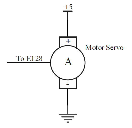
SERVO MOTOR | Launcher aim, Ball receiver, Cloak
To drive motors that will control the ball receiver and the aiming mechanism for the ball launcher. A simple circuit with the servo motor connected to power, ground, and the E128 (output). We used a 360 degree servo for the ball receiver and 180 degree servos for the aiming and cloaking mechanisms. |
|
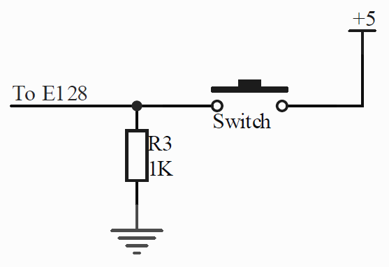
SWITCH | Bump sensors
To use as bump sensors when we arrive at the re-supply depot. The switch is connected to power, a pull down resistor (1K) to ground, and an input to the E128. |
|
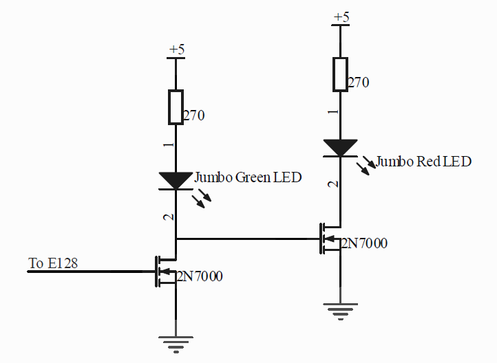
GREEN/RED LEDS | Game On/Off Indicator
To indicate whether the game is in session or if the game is over. When the game is ON, the Green LED is lit by turning on the first 2N7000 n-channel MOSFET, which turns off the second 2N7000 and keeps the Red LED off. When the game is over, the red LED turns on by turning off the first 2N7000 and the second 2N7000 on. |
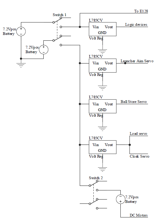
BATTERY/POWER CIRCUIT | Power for all circuits
To power our circuits, we used 3 7.2V batteries. One battery powered the E128 and all the logic devices (with 5V regulator) to isolate the power supply from the motors and minimize noise issues. A second battery, in conjunction with a few 5V regulators, powered the servo motors that were used to aim our launcher, store our Nerf balls, load the launcher, and cloak our bot. To power our DC motors (motors for wheels and the launching mechanism), we put a third battery in series with the second and used PWM signals to regulate the ~14V power source.
To power our circuits, we used 3 7.2V batteries. One battery powered the E128 and all the logic devices (with 5V regulator) to isolate the power supply from the motors and minimize noise issues. A second battery, in conjunction with a few 5V regulators, powered the servo motors that were used to aim our launcher, store our Nerf balls, load the launcher, and cloak our bot. To power our DC motors (motors for wheels and the launching mechanism), we put a third battery in series with the second and used PWM signals to regulate the ~14V power source.